Getting started with the ESP-01
A while ago I bought some ESP-01 modules. I’d read that the ESP8266 was going to be the next thing, and so I bought a bunch - call it and impulse buy. I intended to try them out in a few projects I had on the go at the time. Looking at the date on that article, I’m a bit behind the curve, but finishing my Masters, moving down south, and starting a new job put that on hold. It was only when I moved flat last summer that I rediscovered the bunch of ESP-01 modules sitting at the bottom of my parts bin.
For the uninitiated, the ESP8266 is fundamentally a WiFi-serial bridge - hook it up to a microcontroller and you’re on the internet. Back in 2014, this was how people were putting these cheap WiFi modules to use. A UART and a set of sparsely documented ‘AT’ commands.
But it turns out, inside the ESP8266 lies a powerful 32-bit Xtensa microcontroller running at 80 MHz - plenty of juice for the next ‘Internet of Things’ whatsitmajig. And thats what I’m planning for my stash of ESP-01s. After 2-years, there’s plenty of projects and resources out there.
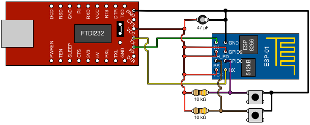
So to the title of this post - how do we getting started? The module runs on 3.3V, and needs a UART for communications. I have a FTDI232 USB-to-serial module, which has Vcc selectable between 3.3V and 5V via a jumper. You’ll also need jumper cables - the ESP has a 4×2 connector, so it’s not breadboard friendly - some female ended jumpers will make connecting up a breeze.

You’ll notice there are two buttons in the circuit. One is connected to ‘Reset’ on the ESP. Start a serial monitor with a baud rate of 74880, and you’ll see the ESP’s startup message - something like blah. The other button changes the boot mode:
| GPIO0 | GPIO2 | Boot Mode |
|---|---|---|
| Low | High | Serial programming |
| High | High | Boot from flash |
So, pressing the GPIO0 button whilst resetting the ESP puts it in serial programming mode - you’ll see a different boot mode on the serial monitor.
Flashing firmware onto the ESP is straight forward, if you have the right tools. The brilliant esptool.py makes uploading your firmware of choice simple. The Python script can be installed with pip install esptool. I downloaded a NodeMCU binary from nodemcu-build.com, and flashed it with esptool.py --port /dev/tty.usbserial-A50285BI write_flash -fm dio 0x00000 nodemcu.bin --verify.
Open up the serial monitor with 115200 baud, and Reset the ESP in flash mode (don’t press the other button). You should see some garbage - the boot message at the wrong baud rate - followed by some info about your NodeMCU build, and finally a > prompt. Type print(‘Hello world’), and you’ll get a reply!
I did have some problems with long wires, and loose connections, but I’m putting that down to cheap jumper wires. Also, the ESP-01s I bought only have a 512kB flash chip, which was not big enough for the NodeMCU firmware I’d built. It’s possible (and quite easy) to upgrade the flash, but that’s for another post.
Next up, I’ll get some code onto the ESP, and get online.
